|
|
||||||||||||
|
|
|
Westchester Web Design |
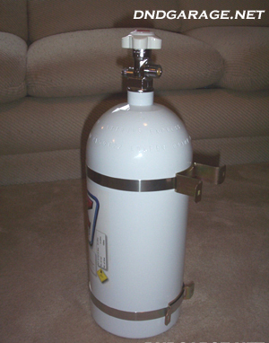
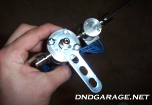
- Slide brackets onto the bottle and tighten (big bracket goes on top, little one goes on bottom).

- Insert the bottle nipple into the bottle nut.
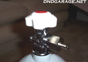
- Tighten the bottle nut and nipple onto the bottle valve.
- Wrap the bottle heater around the bottle and secure it with the velcro straps. NOTE, this is actually the wrong way to mount the bottle heater. You need to mount it so the header is a little bit more towards the bottom of the bottle and flip it around so its facing down and not up like it is now.
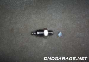
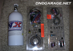
- Find the pressure relief device and the rupture disk.
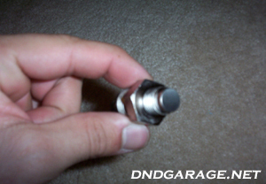
- Install the rupture disk onto the pressure relief device.
- Remove the existing pressure relief device (make sure the existing rupture disk is also removed) and install the new relief device onto the bottle, torque it to 15 ft-lbs.
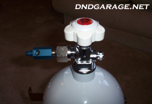
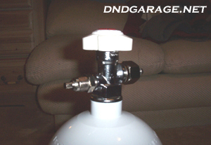
- Install the pressure transducer onto the bottle outlet.
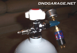
- Install the N20 pressure gauge and bottle heater relay onto the pressure transducer.
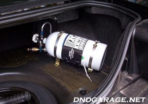
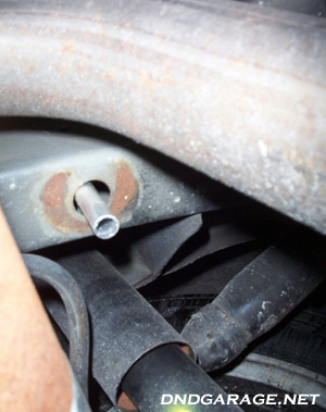
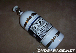
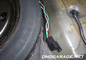
- Be sure to mount the bottle in a place where you will be able to install the blow down tube. In my case I installed it on the pass side as you can see. On both sides of the trunk there are two rubber grommets that you can remove and slide the blow down tube into. I only had to bend the tube a bit to get it to fit right, no cutting was needed. The front of the bottle should be facing the front of the car and the valve outlet should be facing down. To mount the bottle I first placed the bottle in the trunk, with the blow down tube installed through the hole. Then I marked the holes, removed the bottle from the trunk and drilled four holes. To mount the bottle I used 4 small screws that I had left over from my tranny cooler. The screws go down through the trunk, but no where near the gas tank so I dont think you have to drop the tank to mount your bottle, but you should check before drilling. If you use the bolts that come with the kit then youll need to drill four 3/8" holes, everything else is the same.
- You have a couple different options of how to run the N20 feed line, you can either run it under the car, or inside the car. I chose to run it inside the car on the drivers side. (This is also a good time to run the wire to connect your bottle heater relay to your battery. I ran mine right next to the feed line.) Remove the side skirt buy pulling up on it, it might be hard to take off so just pull up hard, you wont brake anything. Remove the drivers side kick panel by taking out the push screw and pulling the panel out.
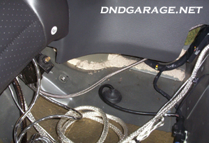
- Remove the rear seat by pushing in the tabs under the seat and pulling up. Just stick a screw driver under the seat and slide it along and youll see where the tabs are. Once you have the seat removed run the rest the line through the side panel, behind the fold down seat, and into the trunk.
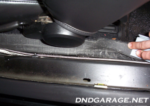
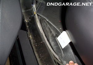
- Pull the carpet up and tuck the feed line under it like you see in the pictures. Be sure that the line isnt being squished and keep it as straight as possible.
-
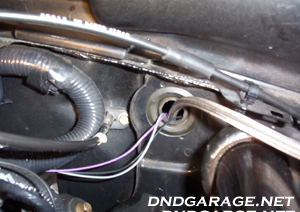
In the firewall there was a rubber grommet to the left of the main one where all the wires are going through. I pulled this off and this is where Ill be running the N20 feed line and any other wires.
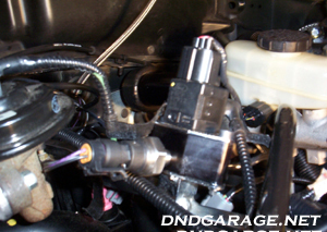
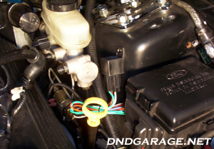
- To install the fuel block remove the two screws that hold down the switch on the drivers side fuel rail. Place some paper towels under the switch before you remove it because some gas will come out. Now pull the switch out of the hole and insert the fuel block. Insert the switch into the top of the fuel block. Now you can install your fuel pressure gauge, FPSS, or the 1/8 NPT plug and fuel hose. I installed my fuel pressure gauge in front and the fuel hose will go in back of the block, but I have to order a fitting to hook up the fuel hose to the block. My FPSS is connected to the fuel solenoid with the blue fitting as you can see in the pictures below.
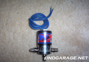
- Apply liquid teflon onto the large 1/4 NPT fitting and install it into the inlet side of the N20 solenoid. Apply liquid teflon onto the 1/8 NPT fitting and install it into the purge side (marked with a P) of the N20 solenoid, this fitting will connect to the purge valve like you see in the picture below, be sure your using the right sized 1/8 NPT fitting. Apply liquid teflon onto the 1/8 NPT fitting and install it into the bottom of the N20 solenoid, this fitting will connect to the N20 hose from your nozzle like you see two pictures below, be sure your using the right sized 1/8 NPT fitting.
- Apply liquid teflon onto the 1/8 NPT fitting that is on the purge side of the N20 solenoid and install the purge valve, but DO NOT install the purge line even though its in the picture.
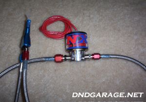
- Now you should have three
fittings left in the EFI kit, this might get confusing so pay attention
and read the whole step before you do anything. Apply a couple drops
of the red thread locker onto the largest of the three fittings
and install it into the IN side of the fuel solenoid. This part will
hook up to your shrader valve, or fuel block using the larger red
hose of the two you have, check the fitting with the hose
and solenoid and make sure you have the right fitting. Apply
a couple drops of the red thread locker onto the next largest
fitting and install it into the OUT side of the fuel solenoid. This
part will hook up to the smaller red hose from your nozzle, check
the fitting with the hose and solenoid and make sure you have
the right fitting. DO NOT tighten the hoses yet. Connect the FPSS
as shown.
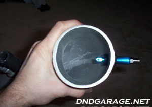
- Installing the nozzle
into the C&L inlet tube turned out to be a pain. The install will
be different for the stock inlet tube, and for the C&L, so Ill
give you both methods. To install it into the stock inlet
tube, remove the inlet tube and drill a 9/16" (might need
to go bigger) hole 2"-6" from the throttle body on a flat surface.
Apply a thin layer of RTV sealer around the adapter and slide it
into the hole from the inside of the tube, apply a thin layer of RTV
on the nut then slide it onto the nozzle. Tighten the nozzle into
the adapter and tighten the nut onto the adapter. The opening of the
nozzle should obviously be facing toward the throttle body. To install
the nozzle onto the C&L inlet tube I ended up cutting off the
little "N20 boss" (because it wouldnt allow the nozzle to go all
the way into the tube) and sanded it down smooth. Then I
had to drill a 39/64" (luckily I had this from my stud install) hole
into the tube to mount the nozzle. Then I applied the RTV
as in the above directions.
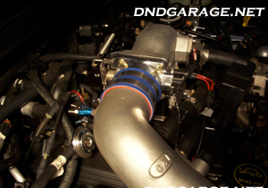
(Nozzle and inlet tube should be installed at this time)
-
Chose your N20 and fuel jets and insert them into the nozzle, refer to the jet chart in the back of the direction book that came with your nitrous kit for different combinations (i.e. for a 100 shot on a 4.6L 2v it would be a #52 N20 jet and a #33 fuel jet).
(Nozzle and inlet tube should be installed at this time)
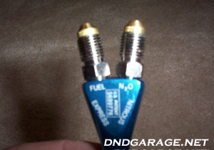
- Once you have inserted
your jets, attach the blue tipped hose to the N20 side and the
red tipped hose to the fuel side on the nozzle.
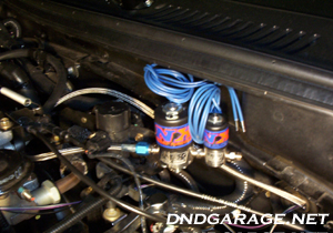
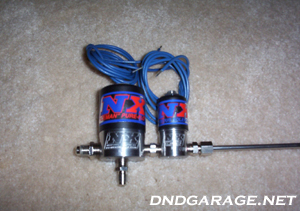
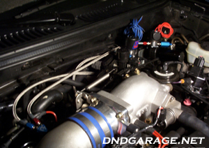
- To install the mounting rod I had to grind it a little with my dremel tool so I could slide it over the fitting on the bottom of the N20 solenoid. Before you mount the rods, go out to your car and see where you want to mount the solenoids. They can me mounted any way, upside down, backwards, etc. Make sure the hoses will reach your mounted points.
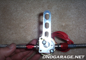
- To install the mount on the fuel solenoid I had to grind it also. Not because I couldnt get it over a fitting (there is none on the bottom), but because the holes were a little off. Before you mount the rods, go out to your car and see where you want to mount the solenoids. They can me mounted any way, upside down, backwards, etc. Make sure the hoses will reach your mounted point.
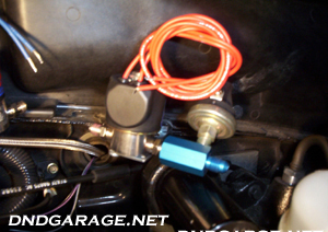
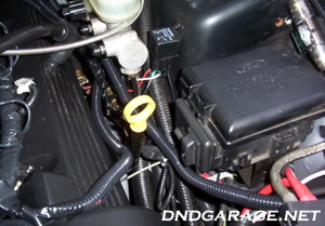
- Before you mount the solenoids make sure that all the hoses will be able to reach. I mounted my solenoids in two existing holes that were on the little lip near the top of the firewall, the N20 solenoid is on the left and the fuel solenoid is on the right. To mount the solenoids I had to make the holes on the firewall lip a little bigger by grinding them. Then I used the bolts/nuts that are supposed to be used to mount the bottle for mounting the solenoids. Once you have the solenoids mounted you can connect and tighten all the hoses. The N20 feed line hooks into the IN side of the N20 solenoid. The blue hose from the N20 side of the nozzle goes into the bottom of the N20 solenoid. The red hose from the fuel side of the nozzle goes into the OUT side of the fuel solenoid. The other red hose goes from the IN side of the fuel solenoid and into the fuel block.
- Now your ready to mount your WOT switch. As you can see I connected the mounting rod to one of the bolts on the plenum, then bent it so the metal rod on the switch would hit a piece near the throttle cable at WOT. Use the bolts and nuts supplied with the kit to mount the switch to the rod.
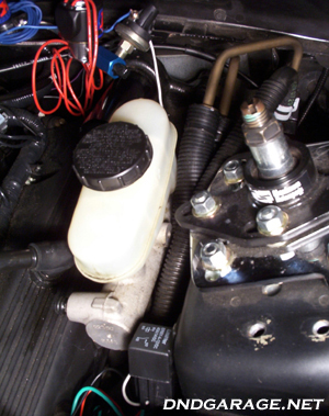
- Once you have everything mounted and the hoses connected, you are ready to wire everything up. First lets mount the solenoid relay. I mounted mine between the fuse box and master cylinder. All you have to do is drill a hole and mount it using one of the supplied screws, easy enough.
- Next attach the white wire from the relay to the side marked NO on your FPSS, then using the blue wire connect it to the side marked C on the FPSS and ground it. I grounded mine to the mounting bolt for the fuel solenoid.
- Now take one wire from each solenoids (fuel and N2o) and splice them together and connect it to the green wire on your relay. Ground the remaining wires on the solenoids (1 for fuel and N2o solenoids). I grounded mine on a bolt inside of the car.
- To wire up the WOT switch you need to connect a wire from one of the terminals on the switch to the red wire on the relay, you can use the blue wire to make the connection. Next, connect a wire from the ACC terminal on your activation switch to the left over terminal on the WOT switch. Find a place to mount the activation switch and connect a wire to the power terminal of the activation switch to a +12v. Then connect a wire to the terminal marked ground on the switch and ground that wire. You can use the blue wire that came with the kit for all these connections (18 gauge wire).
- Now you can mount the relay for your bottle heater. Same thing as the solenoid relay, just drill a hole and mount it using of the screws. The closer to the heater the better.
- To hook up the relay for your bottle heater I connected the black wire on the relay to my battery using the red 12 gauge wire that came with the kit. I ran the wire under the carpet in the trunk, and under the back seat just like the N2o feed line.
- Next, connect the red wire on the relay to the one of the terminals of the heater transducer, then you want to connect the other terminal of the transducer to the other toggle switch in the car. I ran this wire under the back seat and under the carpet, on top of the bump and into my center console since thats where all my switches are. Then you want to connect a wire for power and ground on the switch, the same way as the activation switch.
- Connect the green wire from the relay to the to one of the terminals on the bottle heater, connect the other wire on the heater to a ground. I used the bottle bracket as a ground.
- Last you connect the white wire on the relay to a ground, I also used another bolt on the bracket for this ground.
- Now your ready to wire up your purge switch. I wired this up a little differently then the directions that came with the kit showed. To wire this up all you have to do is connect one of the wires on the purge valve to the push button switch. Then connect the other wire on the purge valve to a ground. Connect the other terminal on the push button switch to a power source.
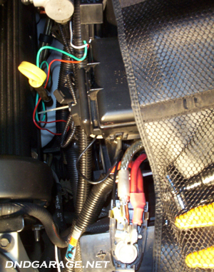
- Last, but certainly not least, your window switch. I decided to use the MSD digital window switch (no tach adapter needed). To wire this up, first connect the black wire on the switch to a ground. Then connect the red wire to a +12v (I used the red wire on the first coil). Now connect the white wire to the green and yellow wire on the first coil. Last connect the yellow wire to the white wire from your solenoid relay. (You can see the window switch on the top right in the picture).
Your nitrous kit is now installed and ready for use. I recommend testing out the switches before use and using a small shot until you get a tune and know everything is working right.
Some other pictures...
I used plastic hose to cover all the wires. This makes the engine bay look very clean, no more wires all over the place.
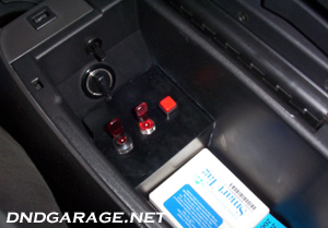
This is the switch panel I made for all my switches. You cant really tell in the picture, but the switches are on and lit up. On the top, above the outlet, you can see my line lock switch.
Write-up
by D&D Auto Detailing: http://www.dndgarage.net/ |