| (Click
thumbnails for full-sized image) |
- Support the car on some combination of jack stands and ramps.
I chose to use ramps to support the rear of the car because
I prefer not to have the car on 4 jackstands. Loosen the
lug nuts on the front rims before raising the car to facilitate
removing the rims once the car is jacked.
- Remove the front
rims from the vehicle using a 13/16" deep socket or
lug wrench that came with the vehicle.
- Disconnect the
negative terminal from the battery using an 8mm socket or
box-end wrench.
|
|
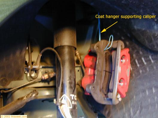
- Remove the brake calipers from the spindles on both sides
of the vehicle using a 15mm socket and a breaker bar to
get the 2 bolts loose. Then use a standard socket wrench
to finish removing the bolts. The calipers need to be hung
out of the way using a coat hanger or a strong piece of
wire. Use a coat hanger, doubled up, to support the caliper
by running the wire through a hole in the strut tower and
twisting the hanger around the top of the strut mount.
|
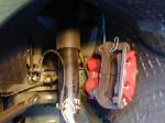
Brake Caliper Removed |
|
- Remove
the rotors from both sides of the vehicle. There are 2 retaining
clips on the rotor hat that have to be removed to get the
rotor off. They can be spun off or simply cut with a pair
of dikes. (They do not need to be reinstalled) I didn't
remove the rotors to do the following 5 steps on the drivers
side, but later I removed them for weight reasons and it
makes the following steps easier. This is why the pictures
show the rotors in place when the springs are already removed.
- Remove the tie-rod
ends from the spindles on both sides of the vehicle. First
remove the cotter-pin holding the nut in place, then use
an 18mm deep socket to remove the nut. Hammer on the top
of the bolt after the nut is removed to drop the end joint
out of the spindle. It helps to turn the wheel outward to
gain access to the end joints.
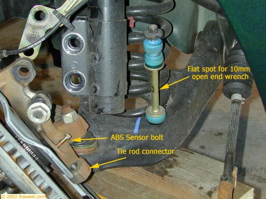
- Remove sway
bar end links on both sides of the vehicle using a 15mm
deep socket on the nut and a 10mm open-end wrench on the
link to prevent it from twisting. There is a flat spot in
the middle of the link where the 10mm open-end wrench fits
|
|
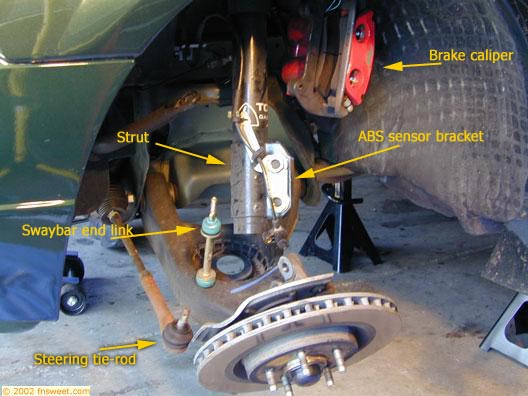
- Remove struts from spindles by placing a jack under the
control arm to jack up the control arm to compress the spring.
First, remove the bracket that holds the ABS sensor harness
in place using a 24mm socket. Move the bracket out of the
way. Then, using a 24mm socket and breaker bar on the nut
and a 21mm socket on the bolt loosen the 2 bolts. Finish
removing the 2 strut bolts holding the strut to the spindle
with a socket wrench. Swing the strut out of the way. Hold
the spindle in place until the ABS sensor can be removed
to prevent damaging the sensor. (The procedure is the same
for both driver and passenger sides.)
|
 |
|
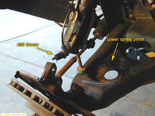
- Remove
ABS sensor from spindle using E8 Torx-bit and hang out of
the way.
|
 |
|
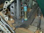
- Remove the coil spring. Make a mark on the lower spring
perch where the last coil ends. This allows the spring to
be reinstalled in the same location. Slowly lower the jack
under the control arm to allow the spring to expand. Allow
the spring to expand to it's fully uncompressed length.
The spring will still be wedged in the spring perch. Push
down on the lower control arm and extract the spring from
it's perch. Be very careful doing this!! Make sure all of
the pressure is off of the spring before pushing down on
the control arm. . (The procedure is the same for both driver
and passenger sides.)
|
 |
|
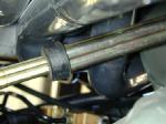
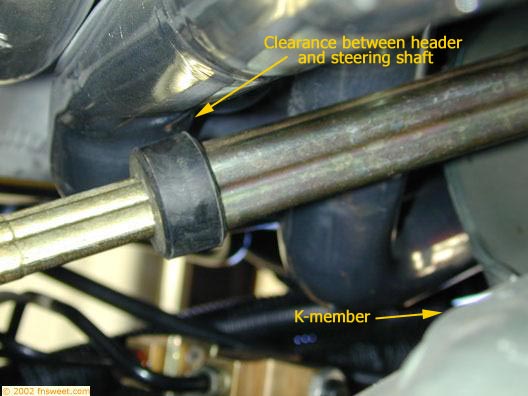
- Remove
the steering shaft nut from the bottom of the shaft where
it connects to the steering box using a long extension and
13mm socket. Turning the steering wheel helps to expose
the bolt. The bolt is accessed through a cutout in the K-member
right behind the spring on the driver's side or from underneath
the car. Pull the shaft off of the steering box. The shaft
is comprised of an inner and outer sleeve. The inner sleeve
can be retracted into the outer sleeve when you pull it
off of the steering box.
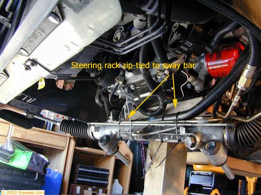
- Remove the
steering rack from the front of the K-member using a 15mm
socket on the 2 front bolts and an 18mm deep socket and
extension on the 2 nuts on rear. Remove the long bolt assemblies.
Pry the steering rack off of the K-member. This may take
some force as the rubber bushings seem to sort of glue themselves
to the K-member. Once the steering rack is pried away hang
it from the sway bar using a coat hanger or zip-ties.
|
 |
|
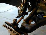
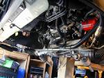
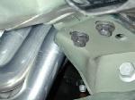
- Remove the 2 bolts from the G-load brace on the rear of
the K-member using a 15mm socket. This gives the access
needed to place a jack under the vehicle and support the
engine from the oil pan.
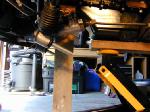
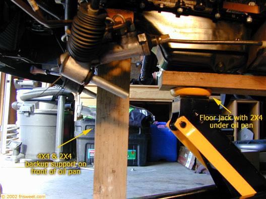
- Support the
motor. Using a floor jack with a 2X6 about 12" long
on top of it, get under the vehicle and jack the board up
directly under the oil pan until it is firmly against the
pan. Use the floor jack with the handle pointing to the
rear of the vehicle to make it easier to remove the K-member
out the front of the car.
|
 |
|
- Remove
the nut attaching the motor mount to the K-member using
an 18mm socket and breaker bar with extensions to loosen
the nut and finish with a socket wrench. The nut is located
behind the spring in the K-member on each side of the vehicle.
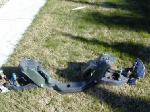
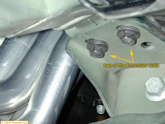
- Remove the K-member.
Support the K-member with a second jack or jack stands.
Use a breaker bar with 18mm and 15mm sockets to loosen the
8 bolts that hold the K-member in place. Finish removing
the bolts with a socket wrench. There are 2 bolts in the
upper spring perch area on both sides of the vehicle. There
are 2 bolts on each side underneath the vehicle in the rear
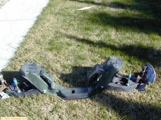
portion of the K-member. Once all 8 of the bolts are removed,
slowly lower the K-member away from the vehicle making sure
it is not getting hung up on anything. After the K-member
is dropped away get some help and move it aside and out
of the way. This is a two person job. The K-member is heavy
and awkward. After removing the K-member I added an additional
support under the block for safety reasons. I added a 4X4
piece of wood with a 2X4 lying across the top of it under
the front portion of the oil pan that was exposed after
the removal of the K-member. A second jack or jackstand
could have been used for this purpose.
|
|
|
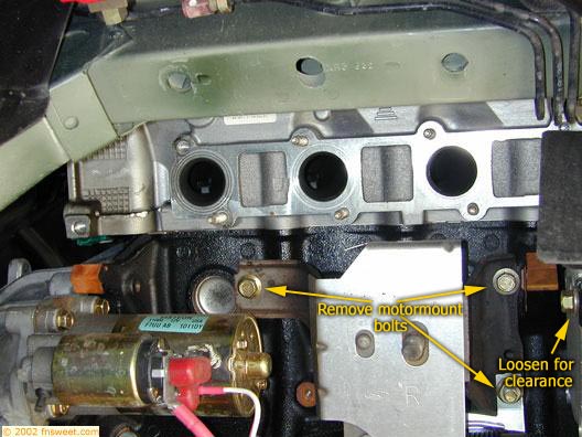
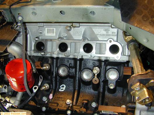
- Remove
the motor mounts from the engine block using 15mm and 13mm
deep sockets. The driver side motor mount has two ground
straps attached to it with 15mm nuts. These need to be removed
to access the 13mm nuts that hold the motor mount to the
block. Each motor mount is held in place by 3 nuts. The
passenger side has a bracket that holds the starter cables
and it needs to be removed before the motor mount nuts can
be accessed.
|
 |
|
- Remove H-pipe/X-pipe
section of the exhaust using a combination of 13mm and 15mm
deep sockets and 15mm box-end wrench. Remove the 2 nuts
from the exhaust manifold studs on each side. Then remove
the 4 nuts and bolts from the rear portion where it connects
to the cat-back. Pull and wiggle the exhaust at the tail
section until it comes free from the cat-back and then slide
it off of the exhaust manifold studs. At this point swap
the O2 sensors from the existing H/ X-pipe to the new shorty
H/X-pipe. The rears are color coded so make sure they go
into the correct side on the new pipe. Put a light coating
of anti-seize on the 02 sensor threads before installing
in the new H/X-pipe.
|
|
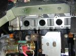
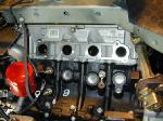
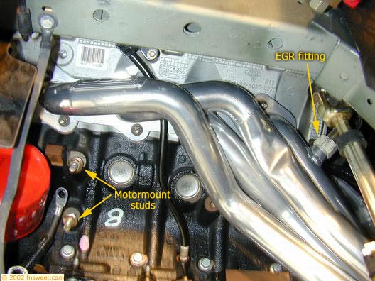
- Remove
exhaust manifolds using a 13mm deep socket and extensions.
It is a straight shot to all 8 of the nuts holding the exhaust
manifolds in place. Some of the studs may come out with
the nuts, but they can be threaded right back in and be
reused. The driver side manifold has the EGR fitting on
the rear of the manifold that requires a large open-ended
wrench or a large crescent wrench. Remove the nut from the
EGR fitting and move the EGR tube out of the way. The exhaust
manifolds slide right off of the studs after the nuts are
removed. Remove the exhaust manifold gaskets if it they
are not going to be reused.
|
 |
|
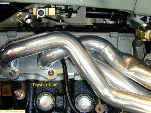
- Remove
the oil dipstick tube using an 8mm socket. The oil dipstick
tube on the drivers side of the vehicle needs to be removed
before the new header can be installed. Pull the dipstick
out of the tube and remove the nut holding the tube in place.
Pull up on the tube and it comes out of the block. The tube
goes into the block about 1 ½-2". I found it
was easier to remove the tube from the block and then pull
it out from underneath the vehicle.
- Install new
gaskets onto studs. I chose to use Bassani header gaskets
when doing the install. They are very high quality copper
and graphite gaskets that should prevent any exhaust leak
from ever occurring. I looked at the stock gaskets and think
these would be a better choice than the gaskets supplied
by BBK if price is a consideration. The Bassani gaskets
were less than $50 and are well worth the money if it means
not having to try to replace gaskets down the road.
|
|
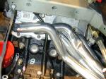
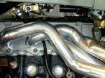
- Install
headers. A little note: it is a good idea to stuff a rag
between the header pipes down by the collector before installing
to prevent dropped nuts/bolts from getting wedged down by
the collector. (it happened to me twice) Slide the header
flange over the studs and gasket. Reattach the EGR tube
on the driver's side. This helps hold the header in place
while the other bolts are being threaded on. Finger-tighten
a few nuts while supporting the header to prevent it from
falling back off. On the driver's side the header tubes
interfere with the two bottom rear studs. This requires
the second stud in from the rear to be shaved down. Using
a Dremel tool to cut off the portion of the stud without
threads gives the necessary clearance. The rear stud can
not be used at all. Use an 8mmX25mmX1.25 thread count bolt
in the lower rear position. The BBK supplied 8mmX20mmX1.25
thread count bolt was to short when used with a lock washer,
and Bassani gasket, which was thicker than stock gasket.
Most of the nuts on the driver side header were easily accessible
and could be tightened with a 13mm deep socket and long
extensions. I used a 13mm open-end wrench to get to a couple
of the top nuts. There was room to move the wrench through
about a ¼- 1/2 of a turn. It was tedious but all
nuts could be tightened fairly easily. Snug all the nuts
down tight enough to squish the gasket and feel tight. Don't
try to tighten them as much as possible because it might
strip the studs out of the block. I sort of did it by feel.
The passenger side header required a little more finesse
to get in. Loosen the mounting bolts on the A/C compressor
a few turns to allow it to move out of the way enough to
get the header flange to slide onto the studs. Lower the
motor about 3 inches to allow access to the top two rear
nuts on the passenger side. There is very little clearance
between the header and frame rail on the passenger side.
Tighten the top two rear nuts with a 13mm open-end wrench
and a lot of patience. Using a 13mm stubby open-end wrench
makes this easier. I used a standard 13mm open-end and could
only turn the nut about an 1/8th of a turn each time because
of interference from the valve cover. Make sure all nuts
are tightened firmly enough to squish gasket and feel snug.
|
 |
|
- Install the oil dipstick tube by sliding it down from the
top of the engine in between the 2nd and 3rd pipe from the
left on the header. The tube will have to be bent slightly
in order for it to clear the header flange. Remove the fuse
box cover in the engine compartment to give the added clearance
needed when sliding the tube back in place. Reinstall the
retaining nut with an 8mm socket. Reinstall dipstick into
tube.
- Install the
motor mounts using 15 mm and 13mm deep sockets and extensions.
Make sure the ground straps and wring harness brackets get
reinstalled on their respective sides. Tighten down the
nuts using the breaker bar for leverage.
- Connect the
O2 sensor wiring harness extension to the connector on the
rear of the block and O2 sensor at the header collector
for each side. Zip-tie the wires away from the headers.
|
 |
|
- Install the K-member. Jack the engine back to its normal
height or a little above. While still supporting the engine
with the floor jack remove the extra support from the oil
pan. Use a floor jack to raise the K-member back into the
original position under the vehicle. Using 15mm and 18mm
sockets reinstall the 8 bolts that hold the K-member in
place. Use a breaker bar for extra leverage to tighten the
bolts.
|
 |
|
- Install
the motor mount bolts. Lower the engine down into position
making sure the motor mounts line up properly. Using an
18mm socket and extension install the bolt that attaches
the motor mount to the K-member. Finish by tightening with
the breaker bar.
- Install steering
rack. Cut the zip-ties holding the steering rack to the
sway bar. Using 15mm socket and 18mm deep socket with extension
reinstall the steering rack onto the K-member. Finish by
tightening the bolts with the breaker bar.
- Reattach steering
shaft. Slide the steering shaft over the fitting on the
steering box and use a 13mm socket to tighten the retaining
bolt.
- Install G-load
brace using 15mm socket. Torque bolts down with breaker
bar.
|
|
|
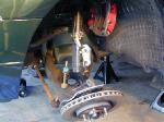
- Install springs. Install the spring back into their perch
by pushing down on the lower control arm and swinging them
in top first. Make sure the springs are aligned with the
pigtail in the same location it was prior to removing. Using
a floor jack under the control arm, jack the control arm
up to compress the spring. Procedure is the same for both
sides
|
|
|
- Reattach
ABS sensor to spindle using E8 Torx-bit and a dab of hi-temp
thread locker.
- Reattach struts
to spindles using 21mm and 24mm sockets. Use a dab of hi-temp
thread locker on the threads of the bolt and torque down
with breaker bar. Reattach the ABS wiring harness bracket
to the strut using a 24mm socket.
- Reattach sway
bar end links using a 15mm deep socket and 10mm open-end
wrench on the flat spot in the middle of the end link to
keep the link from twisting. Tighten the nut until the bushings
are slightly squished.
|
|
|
- Reattach
tie-rods to the spindle. Using an 18mm deep socket tighten
the nut on the end joint. Tighten the nut until the end
joint is pressure fit into the spindle back the nut off
a quarter of a turn then snug it back up. Line up one of
the slots in the nut with the hole that passes through the
end joint and install the cotter-pin.
|
|
|
- Attach
rotors and calipers to spindle. . Slide the rotor onto the
studs and then slide caliper over rotor and attach using
15mm socket. Put a dab of hi-temp thread locker on the bolts
before installing on spindle. Torque the bolts up with the
breaker bar to make sure they are tight.
- Put rims back
on using lug wrench or 13/16" deep socket and torque
lug nuts down to 100 ft/lb.
- Install the
shorty H/X-pipe to the headers and cat-back using a combination
of an 18mm deep socket, 15mm deep socket and, 15mm box-end
wrench. Put a bead of hi-temp RTV gasket maker on the h/x-pipe
where it fits over the header flange to make sure this area
seals up tightly. Fit the pipe up and loosely install the
nuts on the studs at the header collector. Lift the rear
of the pipe into position and install the bolts into the
cat-back portion of the exhaust. Working back-and-forth,
tighten up the nuts and bolts at each connection point until
the ball fitting fits snuggly inside of the exhaust pipe.
Doing this may require help from an assistant to push or
pull on the h/x-pipe assembly so that it mates up with header
flange. In my case the h-pipe need to be spread about an
inch for it to mate up to the collector on the header properly.
- Attach rear
O2 sensors to their respective connector on the tail of
the transmission housing.
|
|
- Reconnect
negative terminal on battery using 8mm socket or box-end
wrench.
- Close the hood
and lower the car down off of the jack stands and ramps.
- Take the car
for a test drive. Listen for exhaust leaks and rattles.
Make sure the car drives straight and feels right. It may
be necessary to take the car to get it aligned if the suspension
was not installed in the exact same location. If it pulls
to one side or the steering wheel is no longer straight
I would recommend having and alignment shop do an alignment.
|
|

